Wall Thickness Analysis
What is Wall Thickness Analysis?
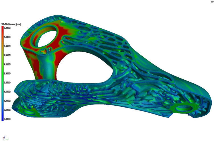
After an accurate surface has been determined, it is possible to calculate the localised wall thickness on part. A wall thickness can be calculated on mesh and volume objects. Wall thicknesses can be calculated using both ray firing and sphere growing methods.
Visualising wall thickness
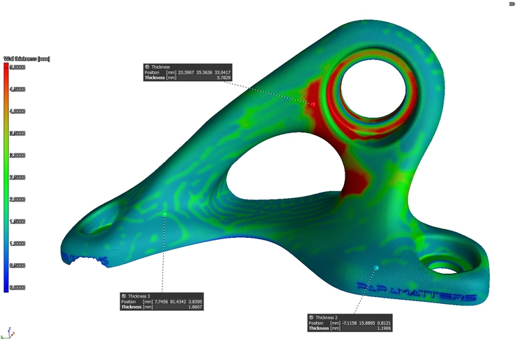
Like a nominal actual comparison, a wall thickness analysis is typically displayed as a colour map on the surface of the part. It is then possible to see at any point what the calculated wall thickness is in that area.
While viewing the 2D slices a whisker plot which represents the wall thickness is visible.
Analytical Information
Discrete points can be selected and the wall thickness measurement can be reported. This is possible in both 3D and 2D. Further to this, a histogram is generated displaying the spread off wall thickness throughout the part.
Further Analysis
Once a wall thickness analysis is conducted it is possible to use it in conjunction with the porosity analysis. Pores can then be classified by the wall thickness area that they are located in.