Reverse Engineering Considerations
The aim of this page is to demonstrate the reverse engineering process to enable you to have a better understanding of how it can be applied to your projects using 3D scanning.
When we first receive an enquiry for a reverse engineering project we consider four elements:
- The component itself
- Size
- Detail
- Material
- Function of the CAD model
- Accuracy required
- As built condition or design intent
In the reverse engineering example below we will go through the complete process.
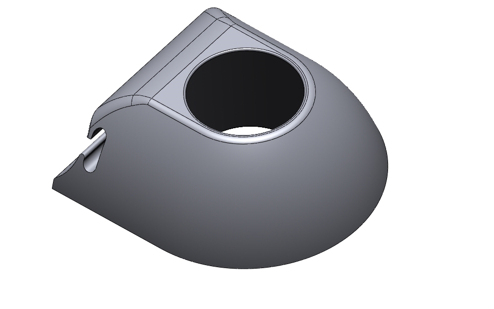
Reverse Engineering – Fuel Tester Splash Guard
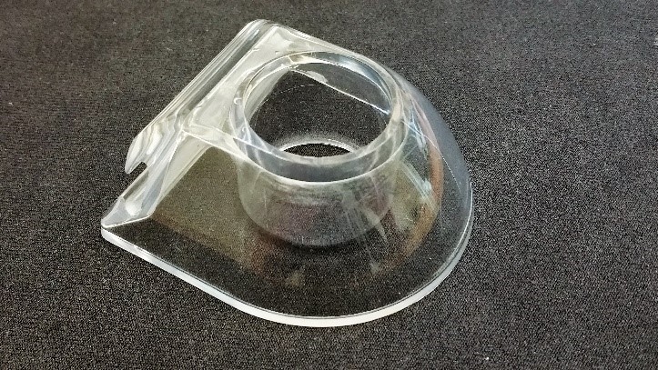
Context: This splash guard fits onto the top of an aircraft fuel tester with the tube of the tester fitting inside of the cylinder.
The project requires us to scan the component and create a CAD model that is symmetrical, whilst maintaining the correct size and shape for the test tube to fit inside the guard. The slot feature to reattach the guard for storage should also be accurately included.
Initial considerations
The component
Size. The size determines which scanning system we use but accuracy also has to be a consideration for this. This component is 60x60x30mm, the portable CMM (arm scanner) will have no problem scanning an object of these dimensions as it is able to scan objects ranging in size between a coin and a car.
Detail. Smaller features or details on the object have to be considered as it will take longer to scan and model and the scanning system has to have the resolution to capture them. In this example, the only small feature is the slot.
Material. The latest generation of arm scanners are able to capture data from a variety of materials including chrome and carbon fibre. Transparent objects will normally need to be sprayed unless we use the CT scanner. In our example, we sprayed the object to make it a matte white colour, perfect for any scanner.
Function of the CAD model
The requirement for this model is to be used for manufacturing and also be able to transfer to another CAD package to be used in an assembly. There are a few techniques we can use to create the model, in this case with this design we will use a solid modelling technique which allows for better functionality for downstream applications.
Accuracy required
Typically, we model to an accuracy of around +/-0.1mm, but this is dependent on the technique used and manufacturing accuracy of the scanned component. In our example, we have to be within +/-0.1mm for the cylinder and slot features, whereas +/-0.25 is acceptable for the rest of the model.
As built or Design Intent
As built modelling would reflect the imperfections of the scanned object, damage can still be ignored but the accuracy is the main goal. Our example is to concentrate on design intent, making everything symmetrical where needed, and dimensions should be made either to a more sensible figure or adjusted to allow for later assembly.
Scanning
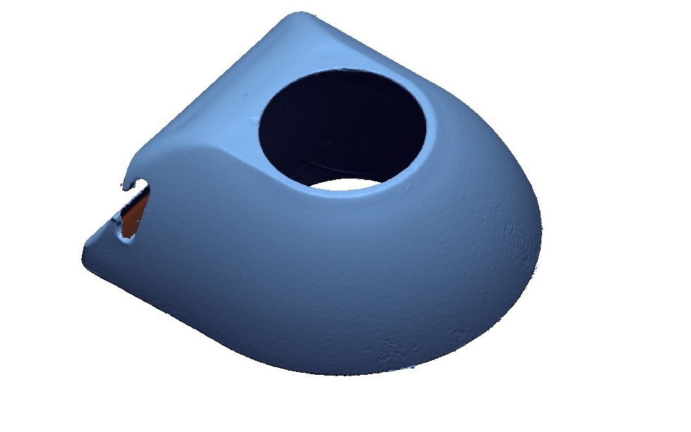
The component was sprayed to reduce the transparency and was quickly scanned using the portable CMM giving the results in the image below. You can see the slot feature wasn’t captured in its entirety, but this is not an issue for reverse engineering if we assume the profile is constant.
Reverse Engineering
Using Geomagic Design X, we can create CAD models from scan data using several different techniques. For this example, we used a solid modelling method to create a functional CAD model that goes back to the design intent.
The image below shows one of the sketches used in creating the main shape. You can see a magenta line which is a cross section of the scan data. This is used as a guide when creating the sketches and can actively be used in the sketching process. We have used the magenta line as a guide and then adjusted the dimensions to try and extract the design intent. One change that had to be made was to make the width 31.5mm in each direction from the origin, this induced deviation in the design in the bottom half of the image but is accepted to make it symmetrical.
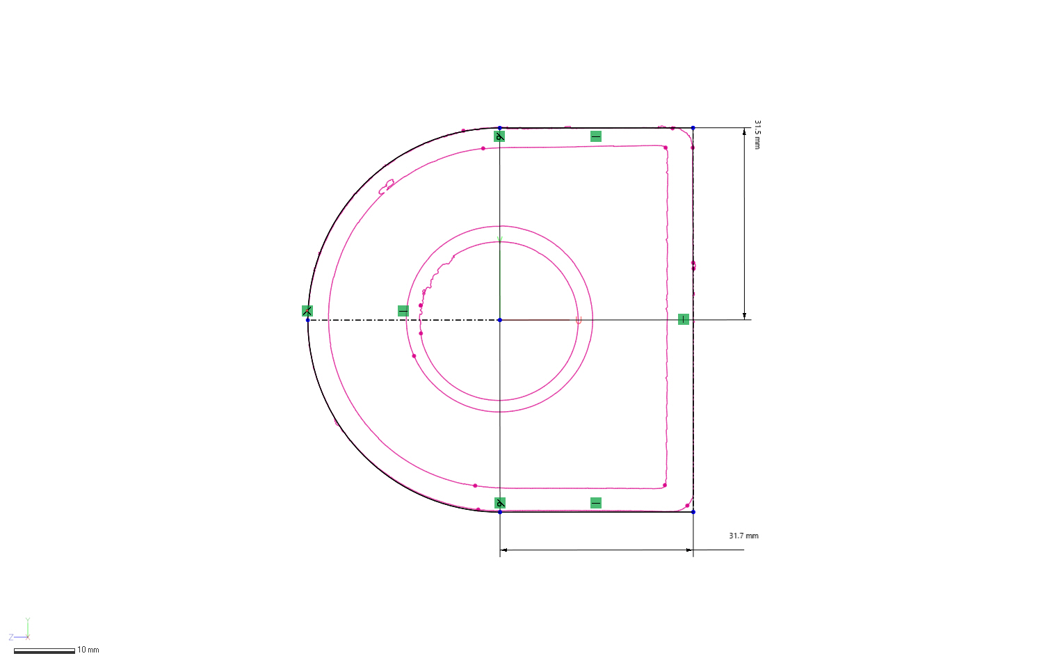
The slot feature was created using a similar process and the profile was extracted from the areas where we had good scan data.
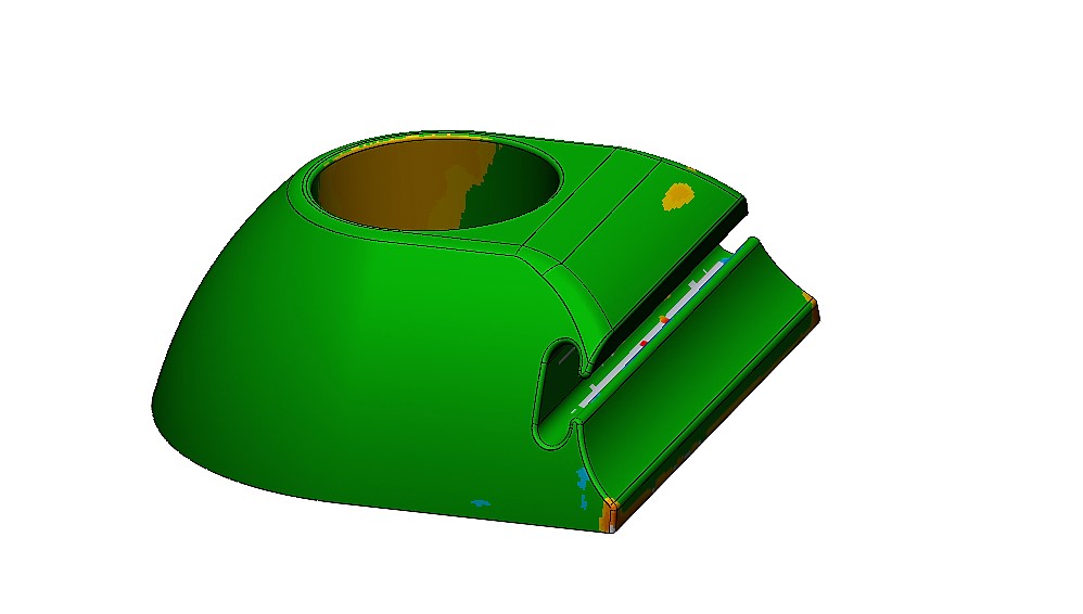
Below we can see the deviation analysis of the completed model. The green area shows an allowable tolerance of +/-0.25mm, we can change these parameters and do further analysis if necessary to satisfy the client of the accuracy and areas that were altered in the reverse engineering process.
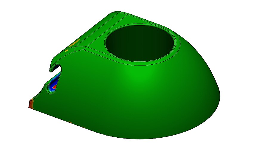
What was first assumed to be a cylinder in the middle of the component turned out to actually be a cone. The deviation in the image below, shows that the conical shape was out of tolerance in the physical part.
Detailed analysis of these features is left to the inspection software package Geomagic Control X.