Meticulous Measurement and Analysis of Components
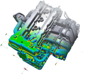
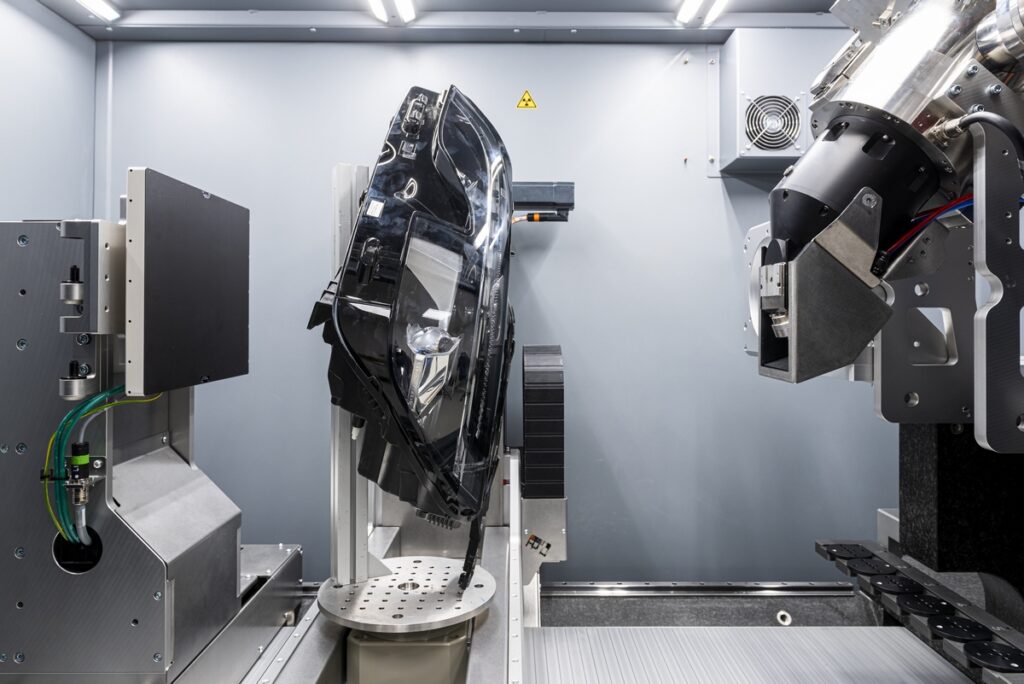
Geometric inspection plays a vital role in ensuring precision and quality across industries. It involves the meticulous measurement and analysis of components, products, or processes to verify their compliance with specifications and standards. At OR3D, we offer comprehensive metrology inspection services aimed at helping businesses achieve excellence and reliability in their manufacturing processes.
Whether you operate in aerospace, automotive, healthcare, or any other industry, OR3D is committed to delivering tailored solutions that drive excellence and innovation in your business.

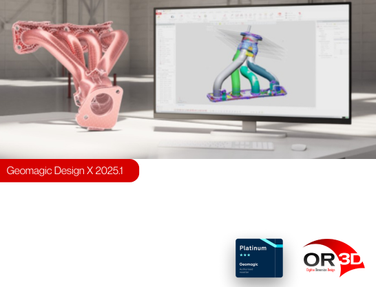
Discover how Geomagic Control X from Oqton, can transform your 3D inspection and metrology processes, delivering accuracy, efficiency and simplicity.
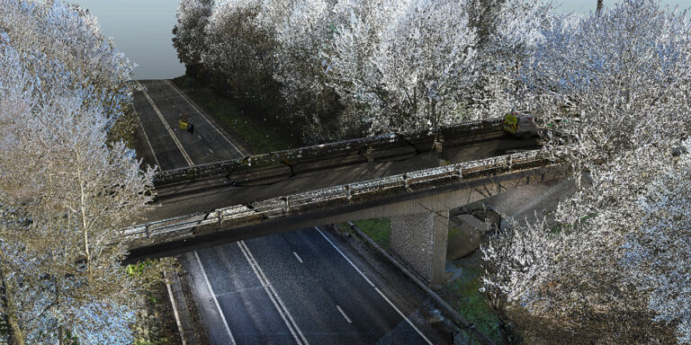
Inspection solutions for your large infrastructure projects such as tunnels, bridges, highways, mines or dams. OR3D has the capability to provide a range of deliverables from 3D CAD design, inspection reports, computer visualisation or simulations.
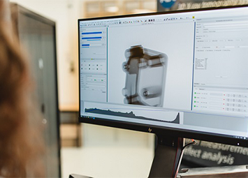
Geomagic Control X inspection software is used to inspect CAD models against scan data and is often used by a range of sectors.
OR3D's comprehensive Knowledge Base Blog, your go-to resource for all things related to 3D Printing, Scanning, CAD Modelling, Reverse Engineering, Robotics, and company announcements. Our knowledge base is designed to empower you with the latest industry insights and news.
Speak to us today on
+44 (0) 1691 777 774

3 Cedar Court, Brynkinalt Business Centre, Chirk, Wrexham, LL14 5NS
Find Us